
Automation
What Vision-Guided Feeding Actually Costs You in Throughput
Adding a camera to a feeder does not slow the feeder down. It changes what you have to feed to hit your rate, and that arithmetic is the part people miss.
Vision on a parts feeder is usually specified for the wrong reason. It gets added because a camera feels like the modern answer to an orientation problem. The right reason is narrower and easier to test for: mechanical tooling has nothing to grab.
When geometry defeats tooling
A tapered tube is the textbook case. It has a nose end and a tail end, and the whole difference between them is a gentle taper along the length. Geometric escapement gates work by catching on a feature — a step, a flat, an offset center of mass. A taper that gradual gives a gate almost nothing to catch, and what little there is stops being reliable once the parts are moving at rate.
We built a pair of step feeders for tapered tubes where one downstream cell would take a part either way round, and the other needed the nose leading every single cycle, no exceptions. The first cell got mechanical tooling and a custom chute, because it did not need to know. The second got a camera.
What the camera does, precisely
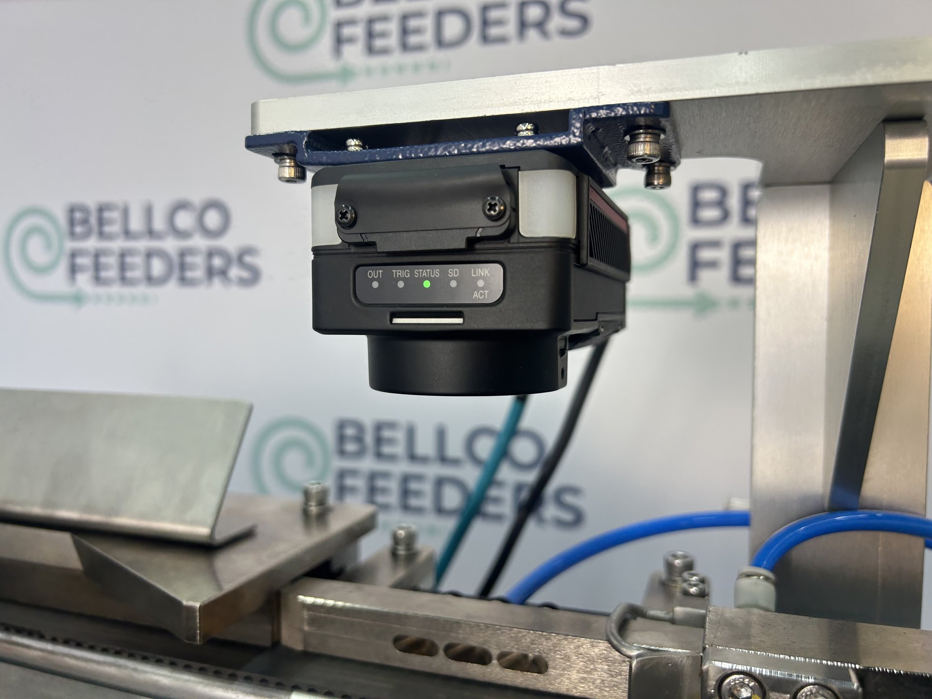
A Keyence IV-4 sits above the linear track and inspects each tube in flight. It identifies which end is leading and signals the system to blow off any tube running tail-first. Correctly oriented parts carry on down a flat-belt conveyor to the escapement and out to the cell.
Read that again, because it is the whole point: the camera does not turn anything around. It rejects. Vision is an inspection and reject stage bolted onto an orientation problem, not a solution to the orientation problem itself.
The arithmetic
Because vision rejects rather than corrects, your delivered rate is the feed rate multiplied by the fraction of parts that happen to arrive facing the right way. If a part comes off the track nose-first roughly half the time, the machine in front of the camera has to run at something like twice the rate you are quoting downstream.
That multiplier has to be in the specification from the first drawing, because it changes the machine:
- The feeder is sized for the higher rate, not the delivered one.
- The hopper has to hold more parts to give the same unattended run time, because it is emptying faster than the delivered rate suggests.
- The track has to carry the extra traffic without backing up into the inspection window.
- The reject path has to clear parts cleanly at rate, every cycle, without jamming the parts still coming.
- Where the rejected parts go — back into the hopper, or into a bin an operator empties — is a decision that belongs in the specification, not at install.
None of that is exotic. All of it is the difference between a system that hits its number and one that hits it only when the hopper is full.
So use tooling where tooling works
Mechanical orientation costs nothing per cycle and rejects nothing that was already correct. If the geometry gives a gate something to catch, that is almost always the better machine: fewer parts fed for the same parts delivered, no camera to keep in calibration, no lighting to protect from a changing environment. Vision is what you spend when the geometry gives tooling nothing — and it is worth every dollar in exactly that case.
The upside nobody asks for
Once a PLC is already in the orientation loop, it can do more than throw parts away. The vision-guided system feeds a custom dual-stage pneumatic escapement that pitches parts either left or right, selected per cycle. Most escapements lock into one fixed escape path for the life of the machine. This one lets the customer feed two downstream destinations from a single feeder, or balance load across parallel cells, without retooling anything.
That turns a feeder that orients parts into a feeder that routes them, and it only exists because the camera had already put a decision point in the line.
Both of those tapered-tube systems run at 33 parts per minute, on 300–400mm linear tracks, from conveyor-fed hoppers holding 720 to 1,000 parts. If you have a part that tooling cannot tell apart end-for-end, send it to us with the rate you need downstream — the first thing we will work out is what the feeder in front of the camera has to do.